The Transformer
Transformer - a term you have probably come across more than once. After all, the transformer is an important component in electrical engineering. But what is a transformer anyway and how is it constructed? In this blog post, we answer all the important questions about the structure, mode of operation and construction of the so-called transformer.
Share
The structure of a transformer
The transformer is an electrotechnical component that creates an electromagnetic coupling between two coils, also known as windings. Originally, the transformer is a voltage transformer and, depending on its size, can transmit anything from the smallest power in microelectronics to the enormous power of power stations and transformer networks.
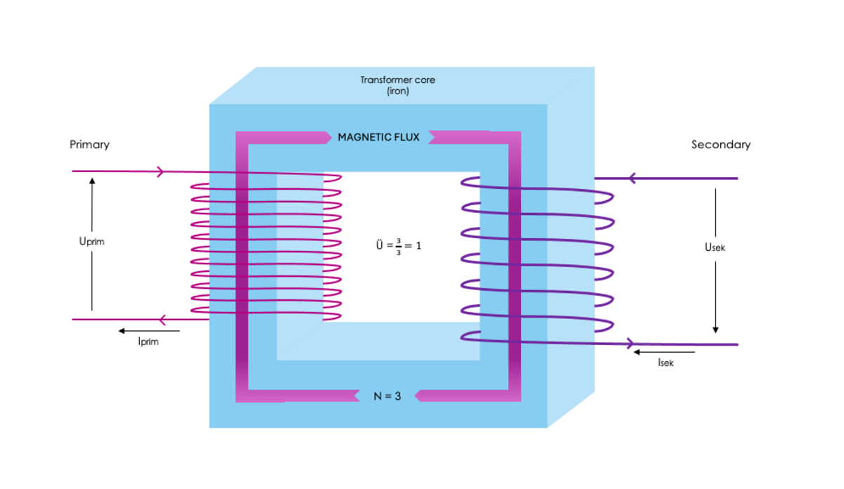
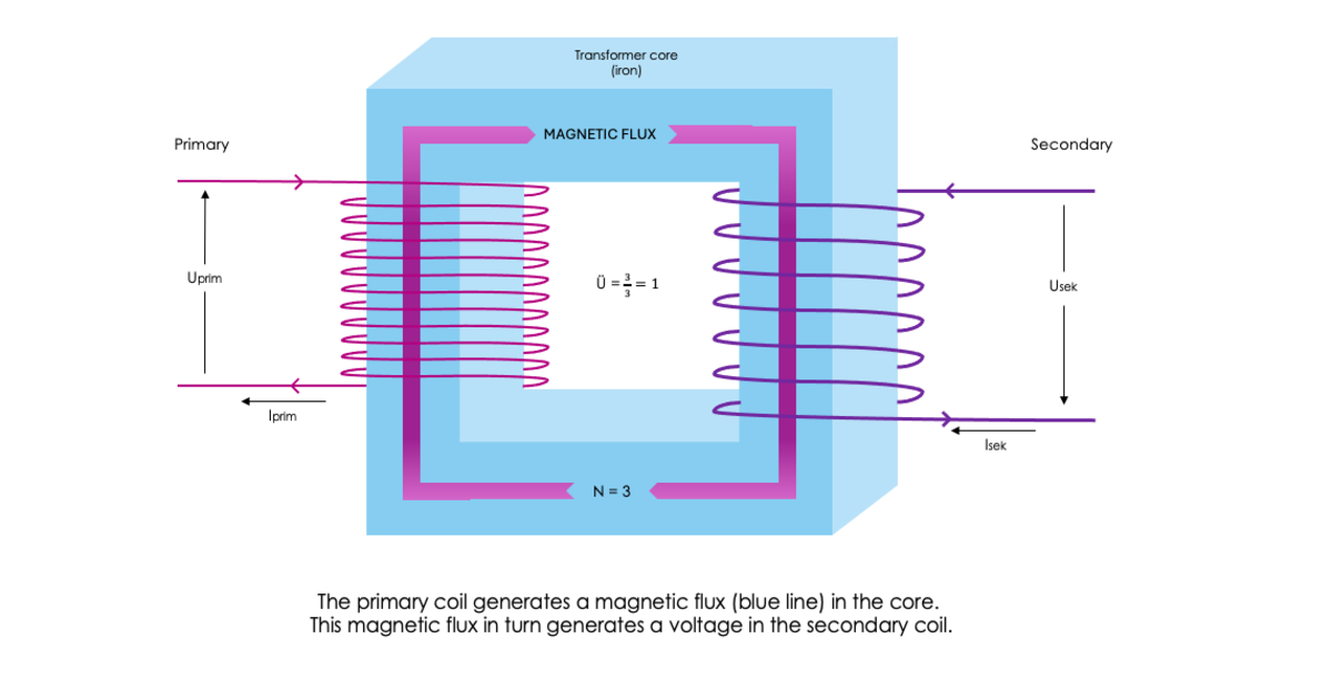
A transformer is constructed as follows:
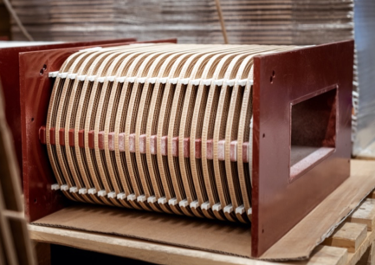
In addition to the ironless transformer, 99% of the heart of the transformer consists of a magnetisable metal core. A variety of metals, e.g. iron sheets, crystalline and nanocrystalline foils, ferrite (sintered powder) etc. can be used as the core. We will come to the reason why metals must be used for the core later in this article.
Furthermore, the transformer consists of an input coil (also called primary) and one or more output coils (secondary). Normally, the number of coils depends on the application. A single-phase transformer usually has two coils; one for the primary side and one for the secondary side. Accordingly, three-phase transformers have six coils; three for the primary side and three for the secondary side. In special applications, such as fan transformers, there may be several coils for the primary and/or secondary side.
These coils, comparable to a roll of string, are one or more windings of a highly conductive non-magnetic material that are wound around the transformer core. The number of windings determines the voltages and the transmittable currents on the primary and secondary sides. This can be visualised using the formula shown on the page.
It is important to know that this formula only applies to the ideal version of a transformer. This means that there are no losses, which is of course not true in reality.
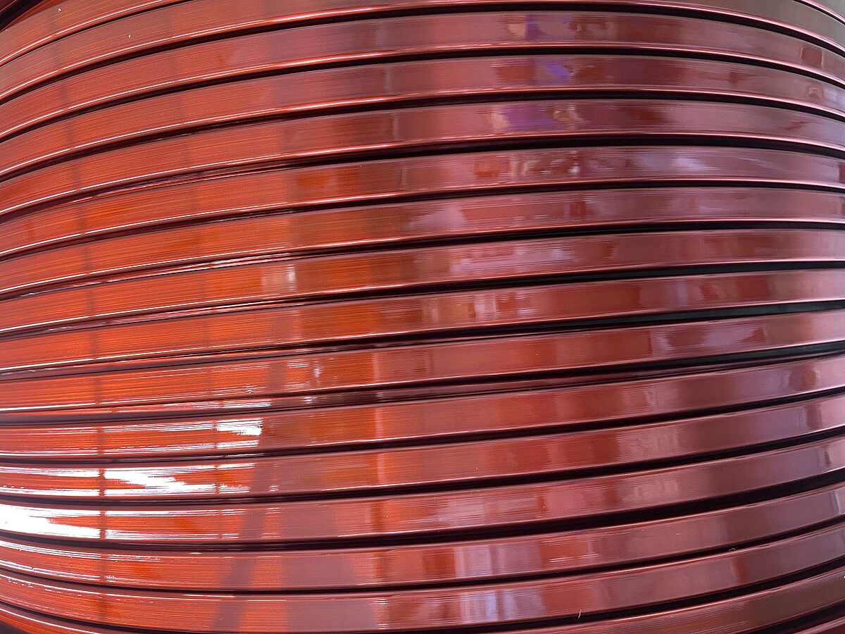
Let's get back to the construction of the transformer: Copper in various forms (foil, round wire, flat wire or stranded wire) is most commonly used to wind the coils. The choice of copper is influenced by various factors. Examples of these are Thermal factors and current density, frequencies and mechanical forces, transmission quality, costs or processability.
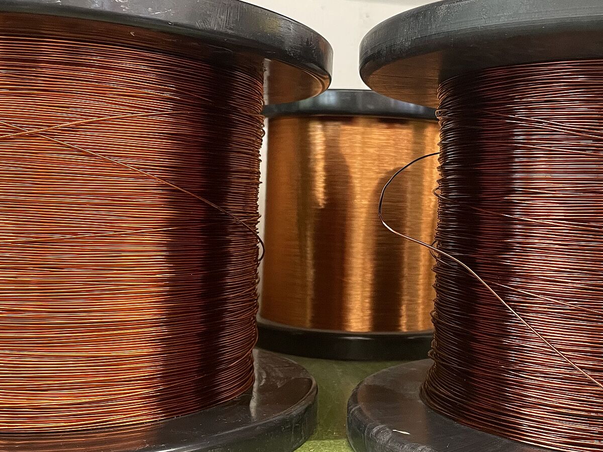
Round wires are easy to wind and inexpensive, but become uneconomical compared to flat wires from a larger diameter due to the space required (also known as the fill factor). The fill factor indicates how much conductor material fits into the winding window. Fill factor 1 means that the entire winding window is filled with the conductor material. However, this is practically impossible to realise.
Metal foil and stranded wire are used to transmit high frequencies. They have the advantage of lower thermal losses.
Aluminium is another conductor material that can be used. Compared to copper, aluminium is cheaper and lighter. The disadvantage of using aluminium is its poorer conductivity, which can lead to higher heat losses.
The coil conductor must be insulated so that no short circuits occur between the individual windings. The wires are often coated with a very thin layer of varnish so that a good fill factor can still be achieved. It should also be noted that a good electrical insulator is unfortunately also a good thermal insulator. For this reason, the insulating layer should not be too thick, as otherwise the heat produced will have difficulty escaping.
Mode of operation of the transformer
The transformer's mode of operation can already be deduced from its name. Transformare is Latin and means "to convert". The task of a transformer is therefore to convert an AC input voltage (primary side) into an AC output voltage (secondary side).
The conversion process is based on the magnetic coupling between the primary and secondary sides. The best magnetic coupling and therefore the best transmission of the desired power is achieved by using a metal core, which is magnetically around 100,000 times more conductive than air. It concentrates the magnetic field of the primary coil and can transfer it almost 1:1 directly to the secondary coil.
This transformer principle for the magnetic transfer of energy is the double law of induction (Faraday's law). In simple terms, it states that a time-varying voltage in a (primary) coil generates a magnetic flux in a permeable (transformer) core through which current flows, and this in turn causes a time-varying magnetic flux in a (secondary) coil. The change in voltage over time is also known as alternating voltage. In Europe, for example, the voltage in the power grid changes at a frequency of 50Hz, i.e. 50 times a second. By way of comparison, you can look at the railway, which often runs at 16.7Hz, or army equipment, which is operated at 200 or 400Hz.
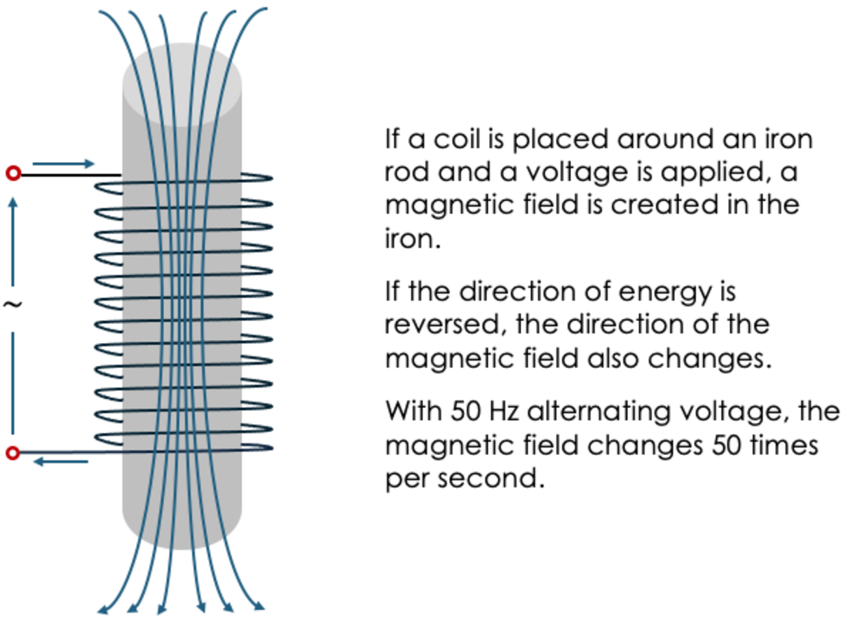
At the same time, this phenomenon also explains why a transformer does not work with DC voltage or why it cannot generate DC voltage itself.
It is important to know that the frequency of the voltage and the level of the primary voltage are decisive for the design of the transformer. It can only work within certain limits of both parameters. If the parameters are changed too much, the transformer can destroy itself. For example, a standard 50 Hz transformer cannot be operated at the output of a frequency converter or at 60 Hz in the USA. It would get too hot and "burn up".
These so-called operating parameters are mainly set via the material properties of the iron core, the hysteresis characteristic. The high magnetic conductivity of the core is an important prerequisite for good coupling. As already described in the construction of the transformer, the choice of material is therefore decisive for the transformer's mode of operation.
While the choice of material lays the foundation for good operation, this is also influenced by the design. The following section explains how.
Construction of the transformer
A transformer is mainly used to convert a given input voltage into a defined output voltage with a required power. But how is such a transformer designed?
The first parameter in the design of a transformer is the size of the iron core, depending on the power to be transmitted and the frequency of the primary voltage. The more iron cross-section through which the winding flows, the more power it can deliver. If we compare this with a river, the larger the river bed, the more water can pass through.
However, the core losses as a function of frequency also play a major role. The specific material-dependent core losses are generally always given in watts/kg. For example, a 1kg transformer core = 2.3 watts, while a core twice as large at 2 kg = 4.6 watts.
An important physical note at this point: as soon as the transformer is connected to a voltage, the transformer core is remagnetised by the AC voltage and the same weight-related core losses always occur. Regardless of whether the transformer is loaded at the output or not. This also means that the core becomes warm to hot, even if no current is flowing at the output!
A very low-loss small core with less weight can have fewer losses (amount of heat) for the same power as a large core, but still have a higher surface temperature. Accordingly, measuring the transformer by hand is not a sign that it must be bad.
The level of induction of this iron core, i.e. how many turns are required for which voltage, now determines the structure of the winding. It is important here that the iron core does not reach saturation even at the 10% grid overvoltage permitted by law or the operator. This would lead to a thermal overload of the core. A lower number of windings leads to more magnetic losses at the same voltage. Here again the comparison to water: If I press more water through the same cross-section, more pressure and temperature is created.
The same applies, by the way, to the winding of the transformer. More current requires more winding cross-section, i.e. thicker wire, in order to keep the temperatures under control. However, thicker wire also requires more space, which makes the transformer larger and more expensive.
The winding ratio between the output voltage and the input voltage is called the transformation ratio. This proportionality of the primary winding determines the output turns ratio. For example, a 230V transformer with 230 primary windings has 115V open circuit voltage at the output with 115 windings (e.g. for USA devices).
The most important design parameters for the quality of the transformer today are increasingly the core losses, the heating of the winding and the optimised size.
Suitable cores, conductors, conductor shapes etc. are selected on the basis of these requirements. The basis for the design is the calculation of the transformer, which is based on the various formulae of electromagnetism and thermodynamics, as explained in more detail in the section"Mode of operation of the transformer".
The manufacturing documents are then drawn up, which represent the exact manufacturing process. This means that the materials and components to be used and how the coil is wound (type of wire, number of windings, where there are air ducts), the mechanical structure of the finished transformer with base angles and connections for the customer, etc. are determined. First the windings are completed, in the case of smaller transformers on standardised coilformers made from a high-voltage-resistant insulating material.
Then the core is built through and around the coil(s). The standard transformer core for our 50/60Hz frequency is usually nested from thin transformer sheets. The reason for this is that in a transformer core, in addition to the desired magnetic field, eddy currents also flow at right angles to the actual direction of flow in order to transmit the energy. In a solid iron block, these have an uninhibited effect and the core boils at a load of around 0.5%. This can be remedied by using thin insulated metal sheets that suppress these eddy currents. The thinner these sheets are, the less eddy losses occur (grain-orientated sheets are the best).
To further improve the magnetic (highly permeable) properties, additives such as silicon are added or other processes are used.
So-called "grain-orientated" large magnetic surfaces are then formed (see image).
Unfortunately, high frequencies also penetrate this insulating barrier of the metal sheets and even better and even thinner, almost glass-like metals are used. If this is no longer sufficient, there are sintered metals, so-called powder cores. Metal powder is mixed with adhesive and poured into a core mould. The tiny balls of powder are insulated from each other, thus reducing the additional high-frequency losses. However, development for high performance is still in its infancy.
We hope that this article has given you an overview of the structure, mode of operation and design of the transformer.


