Chokes
How does a choke differ from a transformer? This is the central topic of this blog post. Among other things, we will introduce the air choke, mains choke, DC choke and the sine filter.
Chokes are coils or inductors that are used to limit electrical currents, for intermediate storage of energy, for impedance matching (also AC resistance) or as filters.
Share
The function of a choke is based on the fundamental principle that a current-carrying conductor generates a magnetic field. This field causes self-induction because the magnetic field influences the coil itself. This results in an induction voltage. Overall, the voltage drop can be described using the following formula:

The first term is the induction voltage uL and the second part describes the ohmic losses in the conductor. It can also be seen that a time-dependent current is necessary for an induction voltage to arise. The inductance is a very important core variable of the choke. It is proportional to the square of the number of windings, as an increase in the number of windings at a constant current means an increase in the magnetic field.
The way a choke works is based on the fact that the induction voltage always counteracts its cause. This means that a state without magnetic excitation is favoured. This is described in Lenz's rule: "The induction current is always directed in such a way that it counteracts the cause of its generation".
The above theory can be used to roughly visualise the process: A disturbance pulse acts on the choke. A pulse has a high temporal change, as one goes from a low value to a high value in a short time. As a result, a voltage is induced in the coil, which counteracts the interference pulse. The induced current flows against the interference pulse. This results in two currents with different directions, which means a reduction in the total current.
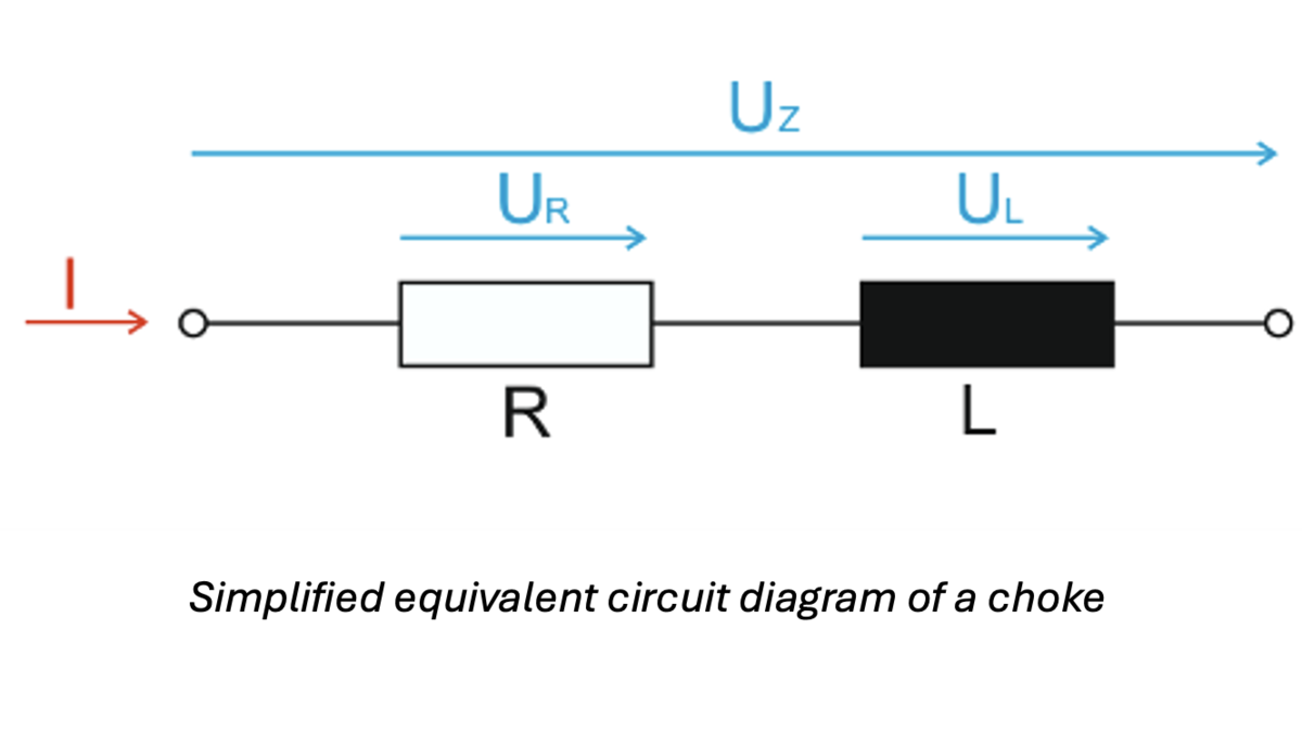
There are different types of chokes due to the wide range of applications. Some of these will be explained later in this blog post. An important characteristic that applies to all choke types is a low resistance, so that there are few losses. This is particularly important as the coil is connected in series and is therefore always active in the network. A simplified circuit diagram of a choke is shown below.
A significant difference to the transformer is that it is connected in series with the other components. In addition, a choke usually only has one winding and not a primary and a secondary winding like a transformer. The basic function of a choke is to suppress interference pulses, radio interference, etc., such as harmonic components of electrical signals.
Air throttle
Air chokes, also known as air coils, are coils that do not have a magnetic core. This means that the core is either made of non-conductive material or has no core at all and therefore only a support for the windings. Air-core coils are mainly used in applications with very high frequencies because no saturation of the core, which can lead to distortion of the current, can occur.
Furthermore, there are no hysteresis losses in an air-core coil, as these are caused by the magnetisation of the core. Nevertheless, the absence of a magnetic core means that the magnetic flux is no longer guided. This results in a relatively high stray field compared to other chokes. In addition, more windings are generally required for the same inductance than for chokes with magnetic cores. This is why the ohmic resistance and the associated power loss are higher. Another characteristic of the air choke is that the inductance is independent of the flowing current. However, the inductance is smaller compared to chokes with cores and therefore the limiting capabilities are lower. Examples of applications for air chokes are short-circuit limiting chokes or chokes for influencing reactive power.
It can be said that most chokes generally have a magnetic core, as fewer windings are required and a higher inductance can be achieved. These magnetic cores usually consist of iron sheets or ferrites, which are used for higher frequency applications. In addition, the core guides the magnetic field so that the stray fields are reduced. In order to avoid saturation, air gaps are built into the core to reduce the magnetic flux density. This also guarantees a linear inductance curve. Furthermore, most of the magnetic energy is then located in the air gap because the highest magnetic field strength occurs in the air gap.
Mains choke (communication choke)
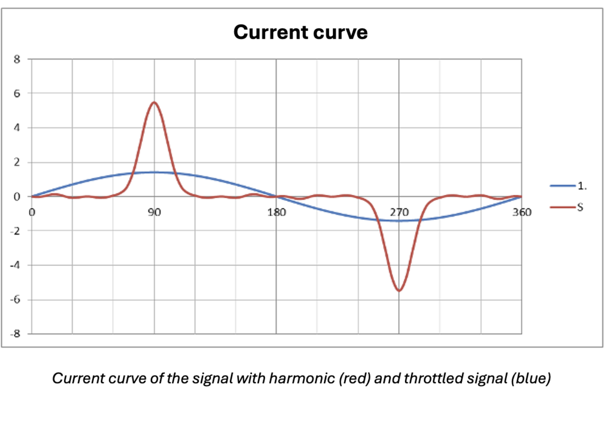
A mains choke is often connected between the mains supply and the inverter. Its task is to smooth current peaks and compensate for the harmonic reactive power so that the output voltage has a pure sinusoidal shape again. In addition, voltage dips in the grid are limited.
Disturbances such as excessive current peaks or voltage dips caused by switching operations or earth faults can damage electrical systems or, in the worst case, lead to a shutdown. For this reason, there is a standard that limits the amplitude of harmonics, as the continuous functioning of the supply network is essential for the infrastructure. It can therefore be said that mains chokes are necessary for the current and future electrical grid.
An example of harmonic suppression can be seen in the next figure.
A special mains choke is the AC choke, which is also called a compensating choke. It is best suited for the 50 Hz grid.
DC choke (smoothing choke)
Smoothing reactors are used for current smoothing in rectifier-fed networks. Their function is illustrated in the following diagram.
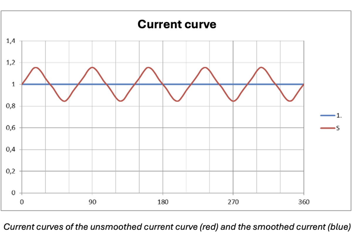
Basically, the aim is to filter out any kind of oscillation in the direct current so that you have a pure DC signal at the output. You need to know that DC currents can also have oscillations and that these are often not wanted in the application. This is why smoothing chokes are used.
In principle, they work in the same way as the others and different smoothing can be achieved with different inductance values. They are used in power electronics, in drives for steel mill rolling mills and mining conveyor systems and high-voltage direct current transmission systems.
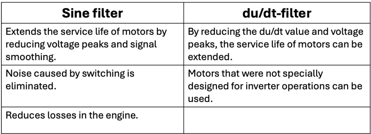
Sine filter and du/dt choke
Both filters act like a low-pass filter and require an additional capacitor:
- At high frequencies, it has a high impedance and therefore these frequencies are blocked
- At low frequencies, it has a low impedance and therefore these frequencies are allowed through.
To understand the general functioning of a low-pass filter, the circuit diagram of a low-pass filter is considered:
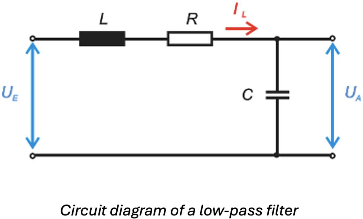
Where UE is the input voltage and UA is the output voltage. In addition, it is important to understand the frequency dependence of the inductance L and the capacitance C. The reactance of the inductance is proportional to the frequency and the capacitive reactance is inversely proportional to the frequency. If a low frequency is now applied, the impedance of the capacitance increases rapidly and can be regarded as an open circuit. As a result, no current can flow and the output voltage is equal to the input voltage. If the frequency increases, the inductive impedance increases until it is so high that it can be regarded as an open circuit. As a result, the total voltage across the inductance drops and the output voltage is zero. This means that high frequencies are not transmitted.
However, the two filters have significant differences:
- With a du/dt filter, the short-circuit voltage(uk) of the inductor is 1-2% of the total voltage, whereas the sine filter has auk of 6-10%.
- The capacitors of the two filters are different: 10-100nF for the du/dt filter and 1-10µF for the sine filter
- The resonant frequency (the frequency at which the reactances of the capacitance and inductance are equal) is significantly higher than the clock frequency for the du/dt filter and lower than the clock frequency for the sine filter, but higher than the nominal frequency
- Due to the lower inductance and capacitance of the du/dt filter, it is fundamentally smaller and less expensive.
- A very important difference is that after a du/dt filter, the voltage waveform is still a pulse and only the current waveform is sinusoidal. In contrast, with a sine filter, both waveforms are sinusoidal at the end.
To illustrate how it works, the following diagram shows the benefits of a sine filter:


